Welcome to the Urban CNC tutorial on using Inkscape to turn any image into a file that can be used to create code for CNC machining. This tutorial will show how to go from a picture to a vector graphic ready for engraving, inlay CNC carving, laser etching, etc. The techniques shown here work for pictures and fancy text.

Why Vector Graphics Are Required For CNC 
Movement of a CNC machine is controlled by programs (G-Code) which move the machine to specific positions or along specific paths. The programs that control a CNC machine are generated mathematically from a digital model of the object or design that is to be created. Therefore, if we want to make something on a CNC machine we first need a scaled, mathematical model of it.
Not all image types are suitable for generating g-code for CNC machines.
Difference between Vector Graphics and Raster Images 
Raster images, (JPEG, BITMAP, PNG, TIFF) are created by a grid of coloured squares, called pixels. The image is made from a fixed number of pixels, but the size of a pixel is not defined. Pixel size is set by the resolution of the raster image based on the number of pixels per inch. The image will appear clearly at its intended resolution but will lose quality when scaled since pixels will be averaged. Also, if the edge of a line were to fall between two pixels, it will get averaged and appear blurry or shaded.
Raster images are the most common digital image and are best for photographs and images with a lot of shading. They are not precise enough for representing a scaled image or a real-world object.
Vector graphics (SVG, DXF, DWG) use mathematical operations to calculate points or edges (paths) of shapes. Because of this, they can be scaled to any size without losing quality. They can also be defined with dimensions such that real-world objects can be represented in true scale. The position of lines and edges is calculated mathematically so the image will be very accurate and independent of resolution.
Vector graphics are best for scalable images like logos or for engineering CAD. A vector graphic can be easily used to generate g-code.

Why Use Inkscape?
Inkscape is an open source (meaning it is free) vector graphic software. It is very similar to Adobe Illustrator or CorelDraw but is typically missing some of the most recent tools. For free software, Inkscape is very powerful and there is a large community of users posting tutorials and YouTube videos.
Inkscape has many tools which can be used to draw vector graphics, but it also has tools that can be used to trace raster images and convert them into vector graphics.
Easy Way To Trace An Image For CNC
Load Raster Image Into Inkscape:
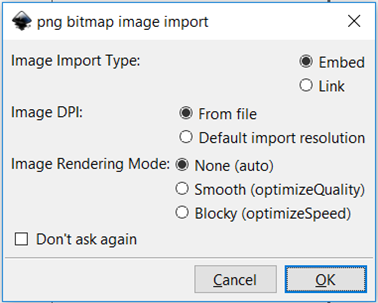
- File > Import
Trace Image to Create Vector
- Select the imported image and convert the raster to a vector
- Path > Trace Bitmap
- Select a tracing mode. Each time you click OK, a new vector path or group of paths will be created. Experiment to see which works best.
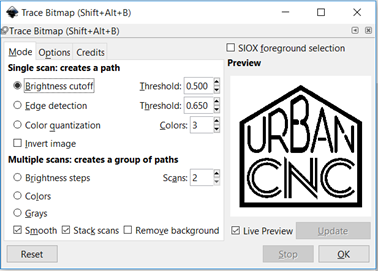
Single Scan
- Results in one set of paths.
- Brightness Cutoff: considers if a pixel should be black or white based on the threshold. (most common)

- Edge Detection: detects an edge by comparing the contrast of adjacent pixels.
- Color Quantization: detects an edge where color changes regardless of brightness or contrast. Determines thresholds based on number of colors to detect.
Multiple Scans
- Multiple Scan will result in a group of paths, set by number of Scans, based on color or brightness.
- Not used often for CNC unless there are different groups of paths desired.
- Be sure to select the vector created and ungroup to select individual scans: Object > Ungroup.
- Brightness Steps: same as brightness cutoff but divides into multiple paths. Example below was pulled apart to show two paths.
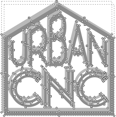
- Colors: Scans sets the number or colors/scans that are output.
- Note: Black and White are colors so setting Scan to 4 will produce 2 color scans.
- Grays: Same as Colors but outputs the scans in grayscale.
- Smooth: Applies a gaussian blur to image before scanning to reduce errors.
- Stack Scans: Fills holes in path.
- Remove Background: Removes background color, leaving transparent background.
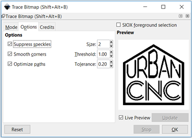
Trace Bitmap Options:
- Suppress Speckles: Excludes groups of pixels smaller than Size.
- Smooth Corners: Controls the amount of smoothing at corners. Higher increases smoothing, zero is no smoothing.
- Optimize Paths: Combines Bezier paths to reduce the number of nodes. Tolerance controls the allowable error. Higher tolerance allows more combining.
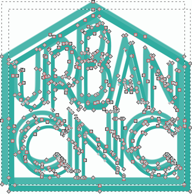
Reduce Number of Nodes:
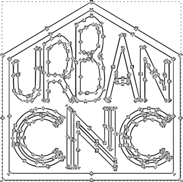
- Tracing can produce more nodes than is necessary to represent the image. Tracing is not perfect, only an approximation, so some editing will be required.
- Additional nodes will slow down CAD and CAM programs when generating G-Code and sometimes cause errors, so simplify the vector graphic when possible.
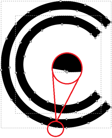
- Duplicate Nodes: Most common error that effects importing into CAD is two nodes on top of each other. Often looks like a node without a black border. Click the node and drag to see if there is a node underneath.
- Manually Delete Notes: Using Edit Paths By Nodes (F2), select and delete nodes. Select the node and press delete. Sometimes it is necessary to adjust remaining nodes after deleting.
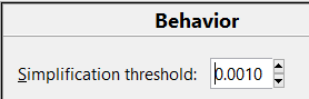
- Simplify Tool: Path > Simplify. Will automatically remove nodes. The amount of simplification, Simplification Threshold, is set in Edit > Preferences > Behavior (I use 0.0010).
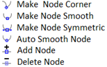
Corner Or Smooth Nodes:
- Depending on the amount of smoothing, most nodes will be generated as corners. (Diamond nodes are corners, Square nodes are smooth).
-
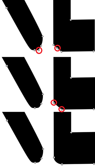
A radius may become a chamfer and a sharp corner may become rounded. Too much simplifying can make this worse. Use the node tools to edit the path where necessary.
- In the example below, the paths should be rounded corners. Step 1: Delete the middle node if possible (this fixed issue on left). Step 2: convert nodes to Smooth (fixed issue on right).
-
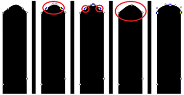
Sometimes, it is necessary to add nodes before deleting to preserve the shape. In the following example, there is no node at the tip of the rounded segment, so we must add one.
- Step 1: select path segment at tip and add a node.
- Step 2: delete the two middle nodes so we now have three nodes.
- Step 3: select the three nodes and convert to smooth.
- Step 4: adjust the node handles to improve shape as desired.
Will This Work for Text and Fancy Fonts?
- Yes, Inkscape can be used to convert almost any font into a vector that can be cut on a CNC machine.
- Pick a cool font, Google Fonts is a great source, and type your message using the Inkscape Text tool.
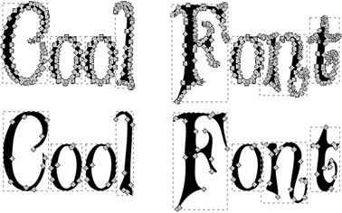
- Select the text and convert to path: Path > Object to Path
- The text is now a vector graphic. Depending on the font, you may get a lot of nodes so consider simplifying.
Harder (Manual) Way to Trace an Image for CNC
- Manual tracing is done by drawing Bezier paths over top of a picture. It is the computer equivalent of putting a blank piece of paper over an image and holding against a bright window to trace.
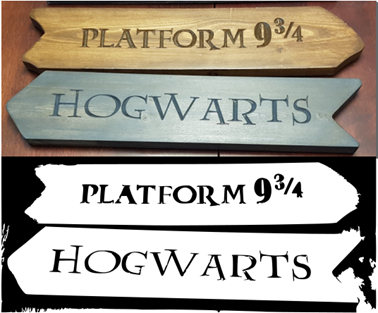
- We will use a less clean image for this example. It is possible to automatically trace this text on the carved signs, since there is a good contrast, but it will not be very clean.
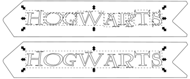
- Separate Text From Outline: If you try to use the node editing tool it will select all the paths as one group.
- First we need to break the paths apart: Path > Break Apart.
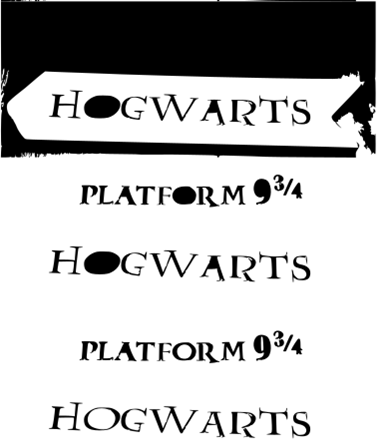
- Next, delete the unwanted paths. You will notice that some paths are now filled in. This is because we separated paths.
- Last step is to recombine paths that are paired together such as the outside and inside path forming the letter ‘O’.
- However, the finished vector still has errors.
- The automatic trace worked but it will need a lot of editing to clean up the trace. The original image can pre-processed in Photoshop or Gimp to reduce the number of colours or remove the background. An alternative is to trace manually.

- Select the Draw Bezier tool and begin clicking along the edges you want to trace. BSpline is preferred since it gives the most natural look but it is difficult to use where sharp corners are needed. Depending on the shape a combination of Regular and BSpline paths can be joined together.
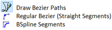
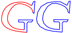
- For the Hogwart’s trace, Regular works best for the letter ‘H’, BSpline works great for the letter ‘O’ and a combination works for the letter ‘G’. For clarity, blue paths are straight, red lines are BSpline.

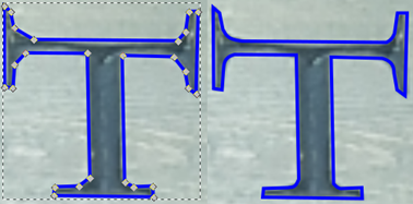
- Once traced, adjustments can be made using the node tools. A straight line can be turned into a radius by clicking and dragging a segment between two points. The letter ‘T’ was drawn with straight lines and radii were made as a chamfer (node at start and end of radius). The chamfer is turned into a radius by dragging the segment until it matches the trace.
Exporting Vector Graphics For CNC
Now that we have our vector graphic looking the way we want we need to do a couple of steps before we export.
Combine Paths and Setup Layers
Depending on how the vector graphic was made there may be several groups of paths. It is best practice to combine the paths so it is easier to move them around the page, select for scaling, etc.
Layers can also be useful when importing into CAD/CAM software. Engraving operations can be on one layer and outline cuts or pockets can be on another. Some software, such as Fusion 360, allow each layer of the imported vector graphic to be its own sketch.
- Holding down the Shift key, select all paths or all paths that will be on the same layer. Box select will also work.
- Optional: Convert to paths: Path > Object to Path
-
Combine the paths: Path > Combine
- Combining without converting object to path:
- Combining after converting object to path:

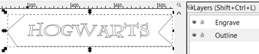
- Open Layers Window: Layer > Layers…
- By default all paths are in Layer 1. Add a new layer for the engraving: Layer > Add Layer
- Rename this layer to Engraving or something that is related to the paths it will contain.
- With the desired paths selected, add them to the layer: Layer > Move Selection to Layer > Select the desired layer
- Rename Layer 1 to Outline or something relative to the paths it contains.
Resize and Scale for Export
- Since we are using vector graphics we can easily scale our artwork to the size of our final product.
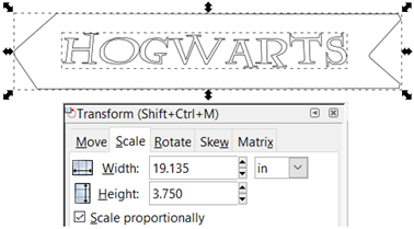
- It is much easier to scale if you have a box or circle around the artwork to act as a reference. For the Hogwarts sign we have the shape of the sign so we scale until that matches the size of the wood board we will be cutting it from.
- Select all the paths and then open the Transform tools: Object > Transform
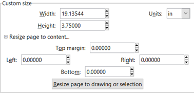
- For the sign, it will be cut from a 3-3/4 inch wide board so the height was set to 3.75 inches. Make sure Scale Proportionally is selected.
- Sketches will import easier if the page is resized to fit the image since the origin coordinate (X0, Y0) will be placed in the lower left corner: File > Document Properties > Resize page to content

Export Vector to DXF
- The finished vector graphic can be exported as either SVG or DXF for use with CAD/CAM software for CNC. SVG will work on most CAD software but DXF is the preferred method as all CAD systems are setup to handle DXF files.
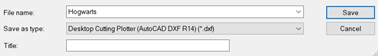
- Export to DXF: File > Save As, Save as Type = ‘Desktop Cutting Plotter (AutoCAD DXF R14) (*.DXF)’
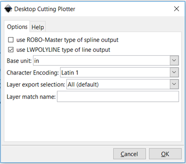
- Set the Base Unit to match your sizing.
- That’s it. You should now have a scaled DXF file with your artwork ready to generate CNC g-code or import into CAD.
-
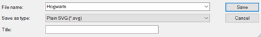
Export as SVG: File > Save As, Save as Type = ‘Plain SVG (*.SVG)’. Make sure you choose Plain SVG vs the Inscape SVG since it tends to cause errors.
- That’ it! You should now have a scaled SWG file with your artwork ready to import into CAD to generate g-code.
Key Takeaways
- Images must be converted to a vector graphic (DXF or SVG) to be use with CNC machines.
- Inkscape is a free software that can be used to automatically or manually trace images and convert to vector graphics.
- Getting great results requires several steps but each step is relatively easy; just takes time and practice.
- Using the techniques presented here it is easy to turn any image into a vector graphic for use on a CNC machine.
Related Tutorials
-
- Will show how to import vector graphics into Fusion 360.
-
- Tricks to improve the quality of traced images and save time.
If you still have questions, please leave a comment below or send us a message through our Contact Page.