Welcome to the Urban CNC Router Build Log.
If you want to learn about the components that make up a CNC router or you are thinking about designing or building your own DIY CNC router this guide will help. Building a DIY CNC router is no simple task but, for me, the hardest part was collecting the required information.
This guide will outline the decisions you need to make and the terminology you will need to learn. Each section can be expanded where I explain my choice. Try clicking on the headings below for dedicated pages with more information.
Success is the result of a great plan.
Check Out the Build Photo Gallery
Determining Design Requirements 
Before you got too excited you need to decide what type of machine you want. This will mostly depend on what you want to cut and how much money you are willing to spend.
What Do We Want To Cut? 
Why limit yourself, let’s cut everything! Wrong…
To cut a material, a sufficient force must be applied to a cutting tool. This force will be transmitted into every component that is connected to the bit (from the router, through the bearings and into the frame). This is important for two reasons:
- It takes motor torque to generate the force.
- Forces cause deflection. Think about every component as a spring.
So, higher cutting force requires more powerful motors and stiffer parts. Your machine will perform much better if it is designed for a purpose instead of trying to do everything.
A good rule of thumb is you can only cut materials that are softer or equal to the main material you use for your machine.
Examples: MDF frames cut wood & plastic, aluminum frames cut wood, plastic & aluminum and steel do frames cut everything.
See What the Materials I Wanted to CutInitially I only wanted to cut wood, so I planned on a budget friendly MDF frame. The more I thought about the projects I wanted to make I realized that most projects would require some plastic or aluminum component like a base, mounts, trim pieces, etc.
This is why I decided to build a machine that would cut wood, plastic and aluminum.
Cutting Area
Bigger isn’t necessarily better!
- A larger cutting area will require a stiffer frame.
- Longer components are more flexible than short components. Remember everything acts like a spring!
- A larger machine will require more shop area. Do you have room for a 4’x8’ machine?
Be honest about the largest size parts you are likely to cut. Aim to accommodate 80-90% of the parts you expect to try. It is better to turn away some of the larger jobs that do not fit your ideal machine instead of compromising your design for 90% of the jobs you want to do.
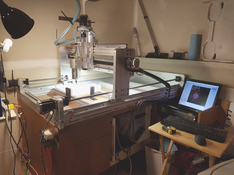
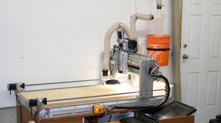
Click to See Why I Chose 25in x 49in Cutting AreaMy main requirement was shop space. I needed to fit my router inside a two-car garage while still parking two cars. You can see the bumper of my car in the lower right corner of the photo.
Most routers are designed with a bed area that is a nice round number typically in increments of 6″. My issue with that is you need a cutting area slightly larger than the part you want to cut. This is because the center of the router bit will cover the cutting area, but it has a radius. Therefore, the largest part you can cut is offset by the diameter of the cutting tool.
Since I wanted to be able to trim the perimeter of a 24″ x 48″ sheet of MDF or paneling (cut a 4’x8’ sheet into four pieces) I chose to increase my cutting area by an extra 1″.
Budget
For most of us, “budget” is a bad word but a budget allows you to spend your money where it has the most benefit. A budget is one of the most important decisions to make since it affects almost every other decision.
Your budget should match your priorities. For example, if your priority is precision then most of your money can be spent on bearings and frame material. But, if time to build and ease of use are a priority, spend your money on prebuilt kits and easy to use software.
My recommendation for budget builds is to save on parts that you can easily upgrade later and spend more of your money on parts you can’t afford to cheap out on.
How I Determined My Budget?My initial budget was a couple thousand dollars because I only wanted to build a router just to learn about electronics (I am a mechanical guy). Once I started working on my design I became worried that I would be disappointed with the result without buying higher quality components.
I ended up taking a more business-oriented approach to the project. Simply, if I spent a bit more money up front, I would end up with a more reliable machine and I would complete it quicker. If I was able to do a couple custom jobs with the router it would easily cover the additional costs.
Spoiler alert: I have no regrets about spending the extra money. At the end of the day, time is money!
Axis Design
Think back to school when you learned how to draw a 2d graph on paper. Points were plotted based on X and Y coordinates. A 3d graph would have a Z axis for height. Look up “cartesian geometry” for a refresher.
A basic CNC machine works the same way. A tool is moved to X, Y and Z coordinates, in either straight or curved lines, based on programmed codes. For a rectangular machine, the short side is typically X, long side is Y and height is Z. More complicated machines can have rotational axis, but this build will focus on the three linear axis. Diagonal and curved motion is achieved by moving two or all three axis at the same time.
Components that make up a CNC axis:
- A straight guide, rail or track to define the trajectory of the axis.
- A bearing or bushing to provide easy movement along the axis.
- Method to push the bearing along the axis.
Important factors to consider when choosing an axis design:
- Strength and stiffness to reduce deflection under load.
- Precision and straightness.
- Load capacity of bearings or bushings.
- Speed rating of bearings or bushings.
Linear bearings
The axis guide and bearing selection are chosen together and are typically described as linear bearings.
There are many choices of linear bearing styles. This is an example where cost is directly related to quality. Cheaper bearings are less accurate and smooth than more expensive bearings.
The following choices are listed from most basic to best performance:
- Roller (skate) bearings on flat bar or pipe.
- V-bearings on angle iron or v-track.
- Supported & Unsupported Linear Ball Bearings.
- Profile Linear Rail Guides.
Do your research and select based on required accuracy and budget.
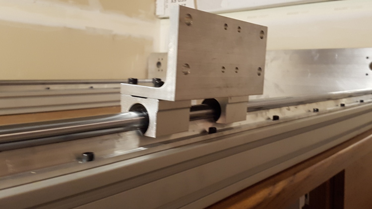
Why I Chose Supported Linear Ball BearingsI settled on supported linear ball bearings for my build. I wanted to use profile linear rail guides because they are the best choice for CNC but, based on my load calculations and required accuracy, the supported linear bearings were sufficient.
The downside to linear ball bearings is that they are round (cannot resist torque about axis). The additional downside of supported versus unsupported is that there is an opening which causes them to flex under side loading. This trade off is fine because the support means that the rail will not sag over a longer distance. The upside for me is I was able to get the accuracy I required at a much cheaper price than the profile linear guide rails. I used those savings to add my favorite component as you will read later.
Ball screw vs Lead Screw or Rack & Pinion
The three most common methods of moving a CNC machine are Lead Screws, Ball Screws and Rack & Pinion. Timing belts and chains are also used on smaller machines like engravers or 3d printers, but I won’t be covering them since are limited by accuracy and load capacity.
Lead Screws:
- Transmits rotation to axial motion using male threads on a shaft and female threads in a translating nut.
- Can be as simple as a threaded rod or more commonly an ACME Screw.
- Typically, less accurate and have high friction losses due to sliding between the male and female threads.
- More suitable for intermittent motion and slow speeds.
Ball Screws:
- Like a Lead Screw but ball bearings replace the female threads in the nut.
- Ball screws are more precise and require less motor torque to turn.
- Speed is limited at longer lengths due to whipping.
Rack & Pinion:
- Linear translation through a rotating gear (pinion) running along a linear gear (rack).
- Can transmit high loads but must deal with at least some backlash in the gears.
- Not limited by length or speed (no whipping).
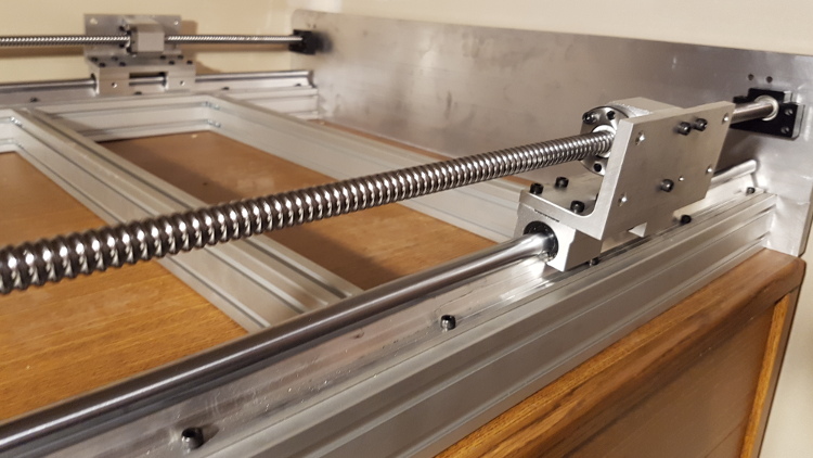
I decided to go with ball screws for my build because my primary focus was precision and accuracy. I would rather sacrifice cutting speed to improve accuracy. Besides, my longest axis is 49 inches, so I wasn’t too worried about whipping.
I selected 1605 ball screws with an anti-backlash nut (16mm thread, 5mm pitch). 16mm was the smallest I thought I could go without worrying too much about whipping. I do notice whipping at around 900rpm which is also where torque really drops off for a stepper motor.
I debated between the 5mm pitch and 10mm pitch for a while. The 10mm pitch would have allowed much quicker speeds but since my goal was precision I decided on the 5mm pitch. I will probably buy 10mm ball screws at some point to do a comparison test but for now I cut up to 150 inches per min (IPM). Most of the time I am cutting at 100 IPM.
Drive Motors & Motor Drivers
To make the machine move we need motors and electronics to control the motors.
A conventional electric motor will simply rotate while powered, typically at a desired speed, with no regard to how many times it has rotated. This doesn’t work well for CNC machines because we need to precisely control how much the motor rotates to achieve our desired position or movement. For this we need a motor that moves in set increments such as a stepper motor or a servo motor.
The following basic components are required:
- Electric Motor.
- Motor Controller (generates the steps or position signals).
- Motor Driver (regulates the current to the motor in response to the steps or position signals).
Drive Motors
Drive motors are sized according to their frame size (think cross section) and identified by a Nema standard (Nema 17, 23, 34, etc). This allows them to have standard mounting from one manufacturer to another.
When choosing a drive motor consider the torque and speed you require. Make sure you have extra torque available to accelerate your machine. A heavier machine will require more torque than lighter machine operating at the same cutting speeds since every direction change requires acceleration.
Stepper Motors
- Brushless DC motors that move in a set rotational increment in response to a pulse (step).
- Commonly have 200 steps per rotation (1.8degree per step).
- Each pulse sent to the stepper motor will result in moving one step increment and holding that position.
- Micro-stepping allows partial steps to get smaller step increments (1/2, 1/4, 1/8, 1/10, etc) resulting in higher precision.
- Control is “open loop” which means there is no feedback to measure the position or confirm movement.
- Missed steps, which can occur under high loads, are not detected and will contribute to positional error.
- Typically limited to less than 1000 rpm before torque begins to drop off.
Servos
- Servo motors have encoders which measure their position.
- Motor position is controlled by comparing the current motor position with the commanded position (closed loop).
- Since servo motors are “closed loop” positional errors do not occur undetected.
- Servos are more expensive & require more complex electronics and software.
- Servo motors are typically high-speed motors so will need gearing to operate at slow speeds.
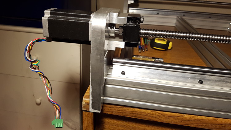
For my project I chose 495oz-in Nema 23 stepper motors. I couldn’t justify the additional cost for the motors and equipment to run servos or the added complexity. For most routing and engraving operations, a stepper motor will work perfectly.
I was worried about missing steps, so I made sure I had more than enough torque and used conservative acceleration. Stepper motors are at risk of missing steps when the load is close to or exceeding their torque rating so keeping accelerations a bit slower will help with that.
I am using ball screws, so my speeds are relatively slow meaning I would have needed a gearbox to use a servo. Perhaps servos would be a good solution for a large, fast rack & pinion setup but I didn’t see the benefits for a smaller machine.
Motor Controller or Motion Controller
The motion controller is where motion signals are generated. The way this is done is slightly different for stepper motors and servo motors, but the idea is the same. Commands from the CNC software are received by the motion controller and appropriate signals are generated and sent to the motor drivers.
Stepper Motion Controller:
- Motion controller outputs a series of pulses in response to commanded movements.
- The motion controller determines the number of steps which will be required to move a requested distance.
- The frequency of the steps determines the speed and acceleration.
- This control is open loop so there is no confirmation that the motor is in the requested position; instead it is assumed.
Servo Motion Controller:
- Motion controller calculates the error between the current motor position and the commanded position received from the CNC software.
- The motion controller generates signals based on the error calculated.
- Acceleration and speed are achieved by sending calculated position signals at specific times to create a motion profile.
- This control is closed loop since the controller can confirm that the servo motor is in position and correct errors.
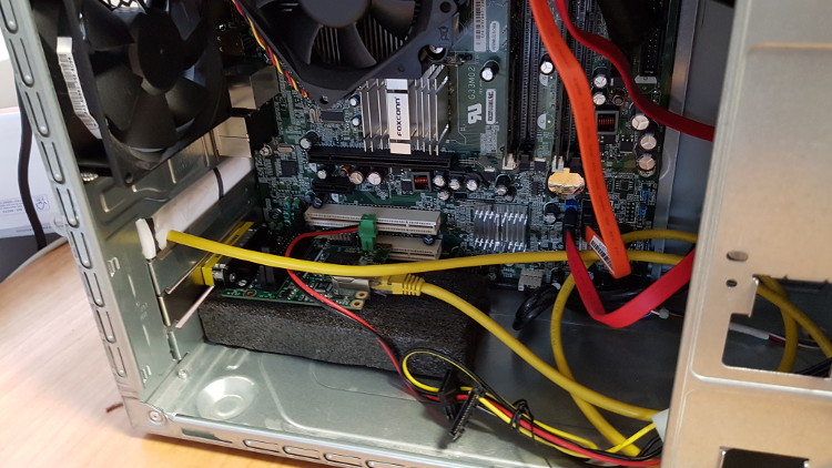
Your motion control can be done on either your computer or on dedicated hardware. I chose to spend a little extra money and use a special card for generating my stepper signals. My rationale was that I could use an old pc to control my CNC router if I left all the high-speed calculations to a dedication card.
I selected the Mesa 7i92 ethernet I/O card. My favorite thing about this card is it connects to the computer through an ethernet cable, so I can easily swap computers. Mesa makes other PCI based cards with the same features but since I was planning on using this machine for experimentation and testing I wanted the option of plugging it into a laptop to try different configurations.
This card also has 34 I/O bits that can be used for step generation, quadrature encoders, PWM, and digital I/O for limit switches, relays, probes, etc. This card is equivalent to having two parallel ports.
Motor Driver
The motor driver controls current flowing to the motor windings. Think of the driver like an amplifier for the motor. Low power signals received from the motion controller (or Mesa Card) are converted into higher power signals which are delivered to the winding of the motor.
Open loop stepper drivers assume that the motor responds consistently. Closed loop servo drivers get feedback from the motor to adjust for changes in load.
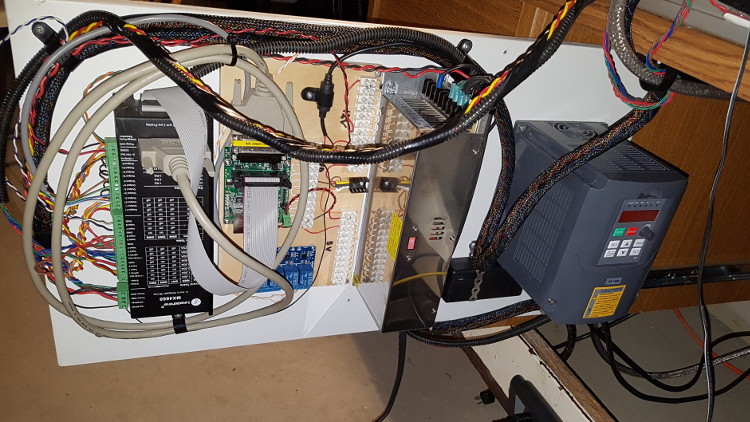
Why I Choose a Leadshine MX4660 Digital DriverOne of the best purchases I made was the Leadshine MX4660 driver. It has four (4) stepper drivers built into one enclose but my favorite part is the integrated breakout board. One relatively compact device can control all my stepper motors as well as handle inputs and outputs for limit switches, probes, relays, spindle speed, etc. It is also expandable for two (2) additional axis!
There are cheaper options available but the MX4660 makes wiring and operation very easy. The digital control and smooth step option resulted in very smooth stepper motion. My stepper motors run slightly above room temperature even after running for half an hour under relatively high load.
Choosing A Router (Spindle)
In machining language, the rotating part of the machine is called a “spindle”. For CNC routers the spindle is the part of the machine that rotates the cutting bits.
Most people seem to use the term “router” to mean the hand-held style of wood routers and “spindle” to describe high speed VFD controlled motors. Both types of motors are “spindles” but for consistency I will follow the same convention.
Wood Router for CNC
- Hand-held wood routers or trimmers can be mounted to a CNC machine to make a simple CNC router.
- Wood routers are high speed, fan cooled, AC induction motors.
- Popular for DIY CNC machines since they are cheap, easily available and simple to setup.
- Wood routers have limited speed control, are loud, not meant for continuous use.
- Fan cooled routers pull air down through the body of the motor for cooling which blows dust and chips away from the bit
- This can get messy on a CNC machine.
CNC Spindle Motor
- CNC spindles are AC induction motors controlled by a Variable Frequency Drive (VFD).
- The VFD precisely controls the current and frequency of the power to the motor to maintain a desired speed.
- Spindle Motors have a large range of speed, are relatively quiet and meant for continuous use.
- CNC Spindle motors come in either air cooled or water cooled.
- More expensive models have automatic tool changer chucks.
My original plan was to start with a smaller wood router just to get started but I was building the CNC router in my garage, so I was concerned about the loud noise annoying my wife and my neighbors.
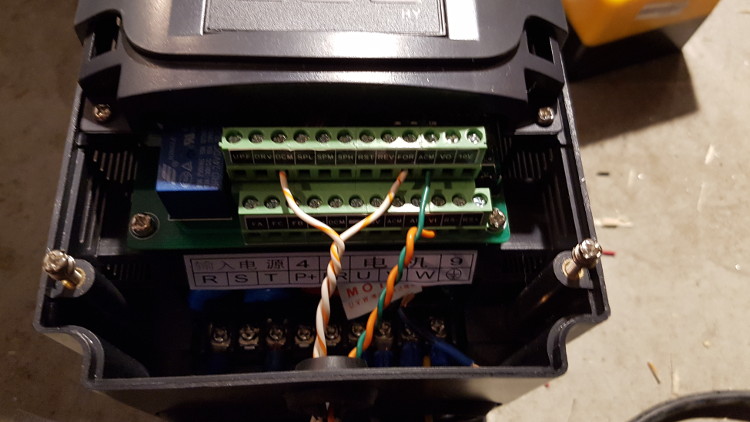
I bought a Huanyang 1.5kW water cooled spindle and VFD. There are a lot of negative reviews online but so far, my setup is working great. I am using the 110V version of the VFD, so I did not need to upgrade any wiring in my garage. I setup a small coolant circuit using liquid cooled computer components and it is working perfectly. The temperature hardly gets above room temperature.
I am powering the spindle on/off and controlling speed from within the g-code using relays.
Overall, I am happy, but I do have a couple regrets:
- My spindle has an ER11 collet which limits me to ¼” shank bits. This covers 90% of what I need but a 3/8″ shank is more versatile and would speed up with roughing. An ER16 collet may have been better.
- I am worried about the quality of the Huanyang VFD. I am not sure I trust the safety ratings, so I plan on upgrading to one I know meets electrical codes in North America.
CNC Control Software
CNC machines are controlled by G-Code and M-Code commands. These commands tell the motion controller what to do. G-Codes control the movement of the machine and M-Codes are miscellaneous functions to perform tool changes, turning on a spindle or coolant, starting or ending a program, etc.
The commands in a CNC program are read and interpreted before being sent to the motion controller.
Several options for CNC control software include free open source (LinuxCNC) and paid software (Mach 3). LinuxCNC and Mach3 are the most common for hobby CNC.
Linuxcnc
- LinuxCNC is a free open source CNC control software.
- It was originally developed for robot control but was adapted for controlling CNC machines.
- Since it is free and runs on Linux it has a slightly longer learning curve, but it is very powerful and customizable.
- LinuxCNC requires a lot of effort to learn and setup but there is a great community of people willing to help.
Mach3
- Mach3 (more recently Mach4) is a very popular paid CNC control software.
- It is not free, but it is relatively cheap.
- Mach3 is easy to learn and is windows based making setup quick.
- Mach3 is not open source so there may be some limitations to how you can customize it.
LinuxCNC was much more difficult to learn that I anticipated. There were several times when I got discouraged and felt stupid. Not only did I need to learn Linux, I also had to learn a lot about the fundamentals of CNC control software to setup and understand LinuxCNC correctly. LinuxCNC is free but that ends up being irrelevant due to the amount of time spent learning it.
Is this where I list my regrets about choosing LinuxCNC? Absolutely not!
LinuxCNC is extremely flexible. Once you wrap your head around how it works you can pretty much make it do anything you like. I was able to customize my homing sequence for a dual motor gantry machine. I added some cool logic to share limit and home switches for multiple axis to save on I/O channels. I wrote custom tool change sequences to do the change in a specific location and automatically measure the tool length offset.
My advice is do not try to take any shortcuts with LinuxCNC. Read as much of the manual as you can handle (yes some of it is pretty boring) and then spend some time reading the LinuxCNC Forums to see what other people have done. LinuxCNC allows you to do whatever you like so it will also allow you to make some big mistakes. Be careful and take your time.
Be honest with yourself: if you are not willing to put in the time to learn LinuxCNC then Mach3 or Mach4 is probably the better solution.
CNC Software Customizations
The whole point of building your own CNC machine is customization. You may think you are doing it to save money but on a basic machine you won’t. The savings come when you customize and add advanced functionality.
Homing
- Homing (aka zeroing) is the sequence the CNC machine follows to determine the 0, 0, 0 coordinate for the machine (G53 coordinate system).
- Should be the first thing done after power up.
- Typically, this involves moving to Z-max, X-min and Y-min.
- If the CNC machine has sensors or switches the homing sequence can be automated. Otherwise if can be manually moved and homed in its current position.
What could you customize?
- Change the order that each axis is homed.
- Setup a homing sequence to auto home and square a dual motor gantry.
- Setup the home position at a custom location other than 0, 0, 0 for setup or storage.
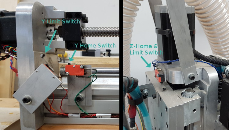
Since I have a dual motor gantry machine I needed to synchronize the homing of the two Y-axis motors. How this works is both motors move towards their own limit switch. When one motor trips its switch it stops and waits for the other to trip. Then they both reverse until their limit switches release. At that point the home position is recorder. By positioning the limit switches properly this causes the gantry to automatically square itself.
To save inputs on my breakout board I wired the X-axis and Z-axis home and limit switches in series. The issue with that is I needed to tell LinuxCNC to ignore the X-axis limit switch while homing the Z-axis and vice versa. I was able to do that with some ‘AND’ and ‘NOT’ logic.
Touch-off Probe
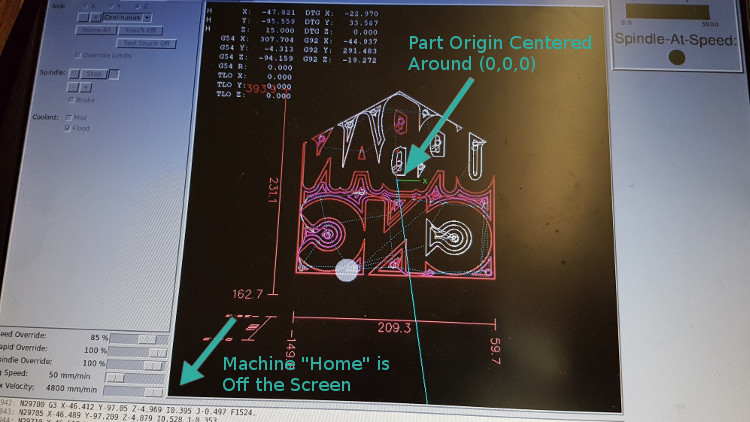
Before machining a part, the CNC controller needs know where the 0, 0, 0 coordinate of the part is. This is different from the machine home and is setup when generating the program code. This process is called “touching off” since you typically jog the machine until the tool tip “touches the origin of the part.
What can you customize?
- Do you want the tool to automatically touch off on the top of your workpiece using a probe?
- Do you prefer to manually jog the tool to touch off?
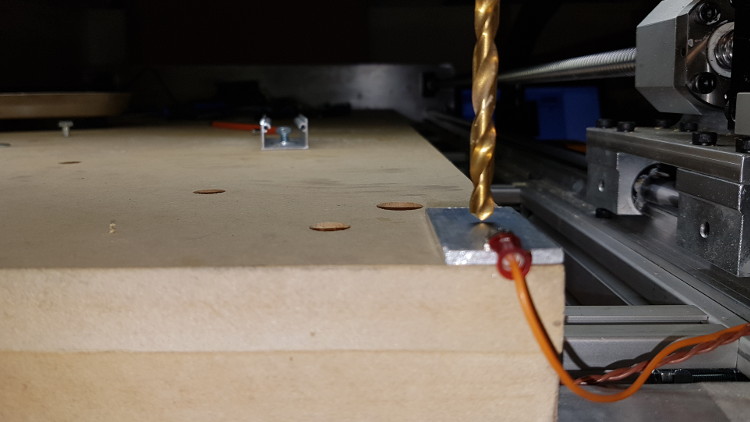
I have a simple conductivity touch plate that I sometimes use to automatically touch off automatically. Most of the time I just do a visual touch-off or use the thin paper trick.
The thin paper trick is relatively reliable and easy to do. This involves slowly jogging the tool down onto the top of the part or table (depending on where the origin is) while sliding a piece of paper under the tool tip. When the paper gets pinched I select the Z touch-off button. I use an old receipt paper since it is thin and doesn’t tear easily.
I am currently designing a 3D touch probe to automate this task.
Tool Change
Most projects will require more than one bit to complete. The program can be broken into several separate programs, one for each tool. Or, one program can include all tools by using a tool change command (M6).
If the spindle has an automatic tool changer the tool change can occur without user input. Otherwise the tool must be changed manually. Most hobby style CNC machines use manual tool changes.
What can you customize?
- Do you want the spindle to move to a predetermined position for tool changing?
- To you want to automatically measure the length of the new tool (TLO)?
- Do you want to automatically control the spindle start/stop, and coolant?
For simple jobs I save separate programs for each tool. But I did setup a semi-automatic tool change sequence. I call it semi-automatic because the only manual part is removing and installing the new tool.
When an M6 tool change code is read, the spindle shuts down and the machine moves to a predetermine position and waits for a tool change to be performed. Once I install the new tool, the spindle moves to a touch-off plate to measure the difference in length between this tool and the previous tool. This measurement is used to apply a tool length offset (TLO) to compensate. Once that is complete, the spindle turns back on and the program resumes with the new tool.
Spindle Speed Control
The simplest way to control the speed of the spindle or router is to manually set the speed. This can also be controlled by the CNC program.
What can you customize?
- Do you want the spindle speed to be controlled from the CNC Control Software?
- Do you want to customize when the spindle turns on/off, pause for speed up?
When you program your CNC code, there are settings that will automatically set the tool speeds. If you do not have automatic speed control setup in your CNC software (LinuxCNC or Mach3) these codes are ignored, and you will need to set the router speed manually. Setting speed manually has the risk you will make a mistake and ruin your cutting bit or workpiece.
The Mesa 7i92 I used has a PWM output that can be used to control spindle speed when connected to the 0-10V output on the Leadshine MX4660. The 0-10V is used to control the speed of the VFD. It works by outputting a pulse width modulated (PWM) duty cycle proportional to the speed commanded as a percentage of the speed range.
Here is an overview of how it works:
- Speed command in RPM is read from the G-Code (S#####).
- The duty cycle is calculated by comparing the commanded speed to the max speed (duty cycle is percentage of time ON vs time OFF).
- PWM signal is output from the Mesa 7i92 to the Leadshine MX4660 to control a variable voltage regulator.
- 10V power is supplied to the Leadshine Mx4660 voltage regulator terminals.
- Speed signal (0-10V) is output from the Leadshine MX4660 to the VFD. The voltage is proportional to the PWM duty cycle.
- VFD frequency is calculated proportional to the speed signal voltage (0V min frequency, 10V max frequency).
Example: “M3 S12000” commands the spindle to turn on and run at 12,000 RPM. Max RPM is 24,000 RPM so PWM duty cycle is 50% producing a 5V speed signal.
That is the simple theory, but I had to apply several corrections to the speed command to get an accurate speed control from Min to Max speed.
- The 0-10V voltage regulator in the Leadshine MX4660 consumes some power so inputting 10V limited the maximum output voltage to 9.1V so I couldn’t reach max speed. The solution was to deliver about 11V to the voltage input on the regulator.
- Control is from Min Speed to Max Speed set on the VFD, not zero to Max Speed so you need to use offsets.
By adjusting the offsets and scaling the requested speed I was able to achieve speed control (+/- 20 RPM) from 7200 RPM to 24,000 RPM.
Dust Collection
This truly is a ‘last but not least’ topic. Your health and safety are important and dust collection is probably one of the most overlooked dangers for CNC routers.
Hazards:
- Fine dust particles can really irritate your eyes, nose and lungs. Sometimes even irritate skin.
- Dust from some woods (especially exotics) are known allergens or even toxins.
- Fine dust can be explosive.
Please take this topic seriously. Keep your work area and shop air clean!
Dust Boots
A dust boot or dust shoe is mounted close to the cutting bit to help suck up dust from cutting. The shape of the boot makes the air flow around the bit more efficient.
The two common styles are fixed height or floating height. Fixed height dust boots mount to the Y-axis at a fixed height off the workpiece. The floating height dust boot mounts to the spindle or Z-axis and moves up and down with the router.
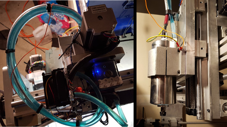
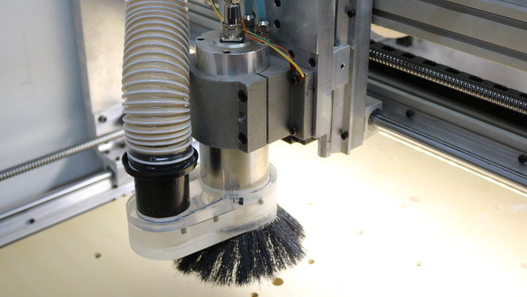
Why I Chose Floating Dust Boot?I chose to mount my dust boot to the spindle body because it seemed easier and the most common approach.
To be honest, I think there are advantages with either design. If you are mostly cutting out 2D profiles in flat sheets, then a fixed height dust boot is probably the most efficient. Since it doesn’t change height it doesn’t need long brush bristles. The floating height dust boot is better for 3D profiles and pockets, but it also works well on flat sheets.
I decided to make my own dust boot because I wanted to cut some acrylic I had picked up. It works well but I want to make a few minor changes to improve the air flow.
Dust Collectors and Vacuums
Dust collectors and vacuums are different tools. Vacuums have high suction but low flow rates while dust collectors have low suction but very high flow rates.
Vacuums are for picking up debris from the ground while dust collectors handle airborne dust particles. Since we are most concerned about airborne dust particles, a dust collector works best while cutting. A vacuum works well for cleaning up finished parts.
For a dust collector to work well, flow restrictions need to be limited as much as possible because there is not a lot pressure to work with.
Dust Filters and Separators
Now that you are collecting the dust what should you do with it?
Most importantly, the dust contaminated air must be filtered before being exhausted. A simple dust filter is not good enough so a HEPA filter should be used. Dust separators are used to remove as much of the dust as possible before reaching the filter. The filter will only need to handle the fine dust, so it doesn’t get clogged up with larger dust.
Why I Choose a Dust Cyclone and Exhaust OutsideFor my dust collection system, I use a Dust Deputy cyclone separator to remove most of the dust from the air and then exhaust the dust collector outside. I decided to exhaust outside because I was concerned about toxic fumes if I were to overheat MDF or plastic. Although unlikely to occur unless the speeds and feeds are incorrect, these fumes would not be captured by a filter.
So far, the dust cyclone appears to be capturing pretty much all the dust. The Dust Deputy Cyclone is sitting on top of a Home Depot bucket.
Key Takeaways
- There are a lot of questions to answer and topics to learn but individually they are not difficult.
- It is both easier and harder than you think but you can do it.
- Use the ‘divide and conquer” technique so it won’t seem overwhelming.
- You now know what you don’t know and what you didn’t know you didn’t know.
If you still have questions, please leave a comment below or send us a message through our Contact Page. Check out our Resources Page for a list of the tools we use and where to find them.
Good Luck!